Modern LED video screens: Characteristics, Technologies, Reasons to Choose – Part 1
The first part of the article deals with those characteristics of modern LED video screens that affect the image quality: controlling brightness with PWM, image creation with time division and refresh rate. We will devote the second part of the article to dynamic brightness range, color rendering and screen contrast, drivers and modern methods of controlling screens, electromagnetic compatibility and electromagnetic interference.
Today we tend to take LED video screens for granted. Indeed, they became common features in our towns and we mostly pay attention to their outward quality parameters. But since our magazine specializes in this technology, we believe time has come to spell out major technical principles of modern LED video screens, those principles that ultimately ensure what millions of people see on screens every day.
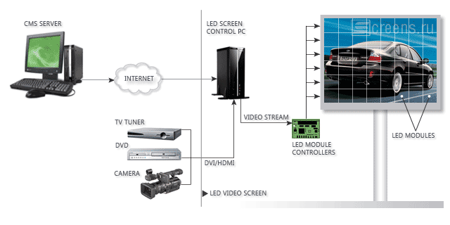
Modern LED video screen is a complex system with enormous number of components. The image quality and operational parameters depend on the quality of each of those components as well as on the functionality of screen control system.

Typical block diagram of a LED video screen
The following LED video screen characteristics are essential from the point of view of image quality:
- LED video screen resolution (so called spatial resolution), in LED video screens it is closely related to distance between pixels or pitch size;
- Maximum brightness (measured in Nits);
- Dynamic brightness range understood as the number of brightness levels that the screen is capable to support (sometimes it is also called radiometric or energy resolution);
- Frame rate measures how often a video source can feed an entire frame of new data to a display, the frequency of frames changing per second (fps) (sometimes referred to as temporal resolution);
- Refresh rate (measured in Hz) is the number of times in a second that a display hardware draws the data, or refreshes the frame (also referred to as temporal resolution);
- Spectral resolution: Color images distinguish light of different spectra. Multi-spectral images resolve even finer differences of spectrum or wavelength than is needed to reproduce color. The term determines how many spectral components create an image;
- Color uniformity throughout the screen;
- White balance and possibility of fine-tuning it;
- Linear perception of brightness – subjective quality of image quality that determines how the human eye distinguishes between adjacent brightness levels both on dark and bright parts of the screen;
- Image contrast;
- Image quality determined by the viewing angle.
Apart from the image quality it is important to consider some key operational parameters of the LED video screen:
- Feedback or monitoring system of screen condition;
- Mature software and comprehensive control system that allow to scaling of the system and construction of LED and LCD video screen networks with remote control via the Internet through in-built informational security subsystem;
- Level of electromagnetic radiation in the form of electromagnetic interference (EMI) from the screen.
Let us consider some of the above parameters in greater detail.
Creation of image on the LED video screen and brightness control
Pulse-Width Modulation (PWM) and refresh rate
The initial image to be displayed is created as a PC file, usually an *.avi or *.mpg clip. The file is decoded by the control PC (or video controller) and transformed into the specialized video stream fed to microchips of constant current drivers. The IC drivers forward constant current to LEDs causing them to glow in a certain spectrum.
PWM – (Pulse-width modulation) is a commonly used technique for controlling various brightness levels. Depending on the brightness level required, the current is forwarded to LEDs intermittently by turning the switch between supply and load on and off at a fast pace. For example, to achieve 50% brightness the current should be forwarded only half of the cycle duration, to reach 25% brightness the current will be switched on for only quarter of the cycle duration. In other words, an LED will operate in a “switched on – switched off” mode where the duration of the “switched on” period will correspond to the brightness level required.
PWM technique ensures that an LED (and the whole video screen) produces a cyclical image. The duration of the minimum cycle (when an LED is switched on and off consecutively) is called a refresh period or refresh rate.
Consider an example: Let us say that the refresh rate of an LED video screen is equal to 100 Hz. To ensure the maximum 100% brightness we need to forward current during the whole period of refresh which is in this case equal to 1/100 s = 10 ms. To reduce brightness by half, the current should be forwarded for 5 ms and then switched off for 5 ms. Then the cycle repeats in the same manner. To achieve only 1% brightness level the current will be forwarded to LEDs during 0.1 ms and the switched off period will last 9.9 ms.
The basic PWM method may be modified and upgraded. Different manufacturers use different terminology: Scrambled PWM (Macroblock), Sequential Split Modulation (Silicon Touch), and Adaptive Pulse Density Modulation (MY’s-Semi). All these functions tend to “spread” the LED switch on period over the whole refresh period. Thus, screen operation at 50% brightness with 100 Hz refresh rate will look like a repeated “1 ms LED on - 1 ms LED off” cycle. It means that for a 50% brightness the refresh period increased five times and is equal to 2 ms. Consequently, refresh rate increased to 500 Hz. This calculation is only true for the 50% brightness. For each brightness pattern there exists a minimum brightness of one impulse (some minimum duration) when LED is switched on, the rest of the time it is switched off.
Thus, strict “traditional” PWM cycles are distorted by modern modified methods. Depending on the brightness level required we can identify shorter periods with higher refresh rate. On a particular LED video screen refresh rate may vary between, let us say, 100 Hz and 1 kHz. It means that during the minimum or maximum brightness the refresh rate is around 100 Hz. But at other brightness levels we encounter periods with higher refresh rate.
Thus, for modified PWM methods the concept of refresh rate becomes rather misleading. However, if we define refresh rate as a minimum period necessary to renew image for all brightness levels, we will avoid all misunderstandings since in this definition refresh rate does not depend on the PWM process.
Interlaced scan-based images and time division on LED video screens
Some LED video screen imaging is structured in such a way as to prevent current supply to all LEDs at once. All LEDs on a video screen are separated into groups (usually, two, four, or eight) which are switched on in turn. That means that methods of creating image described above are applied in turn to different groups of LEDs on a video screen. If the screen has two such groups, the image formation is equivalent to interlaced scanning in analogous TV.
This method is mostly used to make LED video screens cheaper, since this method of image formation needs smaller amount of IC drivers (by two, four or eight times, correspondingly). Since IC drivers contribute approximately 15-20% to screen cost, the economy may be significant. Moreover, the time division method is practically inevitable on high resolution LED video screens because small pitch screens present serious problems in positioning large number of drivers on PCBs and arranging proper heat transfer from IC drivers.
Naturally, this economy leads to lower video screen brightness and lower refresh rate (proportionally to the number of LED groups employed).
Let us say that we have a screen with two LED groups using time division method. The current is supplied to one group to ensure the required brightness. The other group is switched off. After one refresh period the groups alternate: now the second group is powered while the first goes dark. Therefore the period necessary to renew all information on the screen becomes twice longer.
The concept of refresh rate in this case becomes even more subtle. Strictly speaking, the period of refresh or a minimum time needed to renew image on the whole screen doubles. However, for each group the length of image formation period remains unchanged, and we may argue that refresh rate remains the same as before.
LED video screen, refresh rate and human eye
Primarily, refresh rate affects image perception. We usually perceive an image on a screen as smooth and do not notice a flickering effect because the frequency of flickering is rather high. Our visual perception is a psychological as well as physical in nature. The individual flashes of light are summed up into a “smooth” image by our brain. According to the Bloch’s Law, this summing up lasts approximately 10 ms and depends on brightness of light flashes. If light flickers with sufficient frequency (so called threshold CFF – Critical Flicker Frequency), human eye does not notice pulsation according to the Talbot-Plateau Law. The threshold CFF depends on many factors such as the spectrum of the light source, positioning of the light source in relation to the eye, brightness level. However, in normal conditions this frequency never exceeds 100 Hz.
Thus, a human eye will not distinguish any differences in LED video screen images formed with a PWM or modified PWM methods with refresh rates varying from 100 Hz to 1 kHz.
LED screen, refresh rate and a video camera
However, a human eye is not the only instrument that may perceive images. Sometimes we use video cameras to record LED video screens, and video equipment is based on principles drastically different from the one employed by the human brain. This is especially important for all LED video screen installations in the sports stadiums, trade shows or concert halls where events are recorded with cameras. Exposure time or shutter speed in modern video cameras may vary from seconds to a millisecond.
Let us say that we look at a LED screen where image is formed using traditional PWM method with 100 Hz refresh rate. The video screen displays a static image. If we try to record this image with a video camera using a 1/8 second shutter speed (i.e. exposure time of 125 milliseconds) the photo sensor will record light from the screen image produced by 12.5 refresh periods. The LED screen and our video camera are not synchronized and each frame recorded by the camera will correspond to different time related to the beginning and the end of the refresh cycle. But with this high shutter speed there will be no conflict and the camera will record a smooth image of the LED video screen.
If we reduce shutter speed to 1/250 seconds when exposure time equals 4 ms, one camera frame will be 2.5 times shorter than refresh period on the LED video screen. This time the discrepancy between the beginning of the camera frame and beginning of the PWM cycle will be significant. Some frames will correspond to the beginning of the PWM cycle, others to the middle, and others still to the end of the cycle. Each frame will record different light flow and gradually the error accumulates. When we view the recorded video the brightness of frames will be noticeably different. Typically, all objects recorded with short exposure time appear less bright. The camera will record “flickering” effect on the LED video screen. If the exposure time reduced even further we will definitely see some black frames (when the beginning of the camera frame corresponds to the short PWM period when LEDs are switched off) and the recorded video will flicker even more.
Thus, if we use a video camera to record a LED screen with traditional PWM function, the refresh rate should be compatible with or exceed the camera exposure.
On LED video screens with modified PWM function the same logic applies. Since in high brightness mode the turning on time of LEDs is “spread” over the PWM cycle, the recorded image will be more stable compared to traditional PWM function. But at low brightness the situation will remain the same: the recorded image will either lose brightness or will flicker.
As you see without proper synchronization any video recording of a LED screen will result in distortions in recorded image. We can compare this to recording the analogous TV with an analogous camera: the differences in scanning modes of both devices will lead to an effect of diagonal black lines separating TV frames.
Another important issue is the synchronization of LED video screen controllers. Large LED screens are made of blocks (LED modules and/or cabinets) that display imaging generated by different controllers. If these controllers do not synchronize the beginning of the PWM cycle (i.e. the beginning of the cycle on different parts of the screen) we may encounter the following problem: refresh cycle on some parts of the LED screen will correspond to camera frames and on other parts of the screen it will not. If the exposure is compatible with refresh cycle, part of the video screen will seem brighter, another darker. The whole image will consist of dark and bright rectangles and will be uncomfortable to watch.
The cost of LED video screen high refresh
Irrespective of the PWM generation method they all have common features. PWM generation operates on a certain clock rate Fpwm. Let us assume that we have to generate a certain number N of brightness levels. In that case refresh rate Fr cannot exceed Fpwm/N.
Here are some examples to illustrate the above statement:
| PWM clock rate | Brightness levels | Refresh rate |
|---|---|---|
| Fpwm=10 MHz | N=256 (8 bit per channel) | Fr=39 kHz |
| Fpwm=10 MHz | N=1024 (10 bit per channel) | Fr=9.8 kHz |
| Fpwm=10 MHz | N=2048 (11 bit per channel) | Fr=4.9 kHz |
| Fpwm=10 MHz | N=65536 (16 bit per channel) | Fr=152 Hz |
| Fpwm=20 MHz | N=65536 (16 bit per channel) | Fr=305 Hz |
These numbers demonstrate that each LED of video screen follows some independent PWM generation process, i.e. PWM generation method is programmed directly into IC drivers.
With simple and cheap IC drivers, PWM is generated on a controller for the LED video screen. We should then consider how many drivers are linked consecutively and are serviced by one PWM generation process. If one PWM generation scheme requires M 16-output channel drivers, the refresh rate may not exceed Fpwm/(N*M*16, otherwise it leads to significantly lower refresh rate or the need to increase clock frequency.
In case of time division (interlace scanning) the refresh rate falls in proportion to division coefficient.
Thus, to increase refresh rate on LED video screens the following options are available:
- Use of “intelligent” (expensive) drivers;
- Increase of clock rate in the PWM generation process;
- Reducing the number of brightness levels (color depth).
Each method has advantages and shortcomings. The intellectual drivers are much more expensive than simple IC drivers; the rise in clock rate leads to higher power consumption (consequently requires additional measures for heat transfer to avoid overheating); low number of brightness levels negatively affects the image quality.
Conclusion: Refresh on LED video screens
LED video screen manufacturers frequently use refresh rate as a marketing tool when boasting excellent screen quality. The presupposition is that the higher the refresh rate the better is image quality. However, often the numbers serve only to confuse potential customers. For instance, refresh rate of several kHz means that either the modified PWM generation method is used (when refresh rate is in fact different for different brightness levels) or that the color depth is unacceptably low.
We should remember that high refresh rate and high color depth values may only occur at high brightness levels which in itself are a misconception, since a LED video screen should not always operate at 100% capacity.
For the case of interlaced scanning the refresh rate value will only correspond to one PWM cycle for one LED group, while the actual refresh rate for the screen (which affects our perception) will be several times lower.
It is more informative and honest to mention color depth and clock rate for PWM and approximate range of refresh rate for the screen (for example, 200 -1000 Hz) in case of modified PWM screen function. If a LED video screen is based on the time division principle (for example, time division = 1:1 – absence of time division, time division = 1:2 – PWM only operates on half of the screen etc.).
The above parameter is not essential for our perception. Human eye does not register any difference in image quality at frequencies above 100 Hz. Consequently, one should decide if high refresh rate is really necessary and if it is worth while paying extra for it.
Refresh rate and uniformity of recorded screen image are only important in cases where a LED screen frequently becomes an object for video recording (stadiums and concert halls). Therefore, it is better to first conduct some trial recording prior to signing the purchase contract.


